


 中文简体
中文简体 Español
 Français
Designed as a reliable replacement for MERCEDES BENZ Sprinter, Vito, and Viano models equipped with the CDi2.1L engine, the 12V 200A 0124625006 Bosch car alternator for MERCEDES BENZ Sprinter/vito/via...
See Details

Get A Quote
Exploded View of an Alternator: A Part-by-Part Guide for Technicians and Buyers
Oct 09, 2026
An exploded view of an alternator takes a finished unit and pulls it apart along its shaft, floating every component out in the order it fits. Instead of a sealed black box, you get the pulley, the bearings, the claw-pole rotor, the stator, the rectifier and the regulator as separate pieces, each with a number beside it. For technicians, parts buyers and anyone who has watched a battery light flicker on at dusk, that single drawing explains both how the part works and where it usually fails.
This guide walks through the anatomy of a typical alternator exploded view, explains what the labels mean in practice, and shows how the layout shifts between the families you are most likely to see in the workshop, whether you are rebuilding an old core or ordering a replacement.
Content
What an Exploded View Actually Shows
An exploded view is an assembly drawing, not a photograph. The parts are drawn as if pulled apart along the centre line, usually in the sequence a technician would remove them, and each one carries a callout number that matches a parts list. Because it is a technical drawing, it also leaves things out: the fine detail inside a winding, the soldered joints between stator and rectifier, and the exact tolerances of bearings and shafts.
Even so, a well-made diagram tells the whole mechanical story at a glance:
- The drive end: pulley, retaining nut or overrunning decoupler, cooling fan, and the front housing that carries the drive bearing.
- The rotating assembly: the claw-pole rotor with its field winding and the slip rings at its tail.
- The stationary assembly: the stator with its three-phase windings, pressed into the housing or clamped between the two halves.
- The electrical control block: rectifier bridge, voltage regulator, and on brushed units the brush holder.
- The rear end: rear housing, terminal studs, insulator and dust cover.
Two details are worth confirming before you order anything from a drawing. The first is whether the fan is internal or external, since the two designs use different housings and different pulleys. The second is whether the regulator sits on the rear cover or remotely, which decides whether you can service it without opening the unit at all.
Part-by-Part Reference
The table below summarises the components most often labelled in an exploded view of an alternator, together with what each one does and what to look at during a rebuild.
| Component | Function | What to check |
|---|---|---|
| Pulley | Takes drive from the belt and turns the rotor | Groove wear, runout, slipping decoupler |
| Cooling fan | Draws air through the housing | Cracked blades, correct internal or external type |
| Drive-end housing and front bearing | Locates the rotor and carries belt load | Bearing roughness, worn or spun bearing seat |
| Rotor (claw-pole) | Spinning electromagnet that creates the field | Field winding resistance, bent claw fingers |
| Slip rings | Feed field current into the rotating winding | Scoring, deep grooves, heavy brush dust |
| Stator | Three-phase windings that generate the AC output | Continuity to ground, burnt or darkened insulation |
| Rectifier bridge | Converts alternating current into direct current | Diode forward and reverse test, heat damage |
| Voltage regulator | Holds output near 14 V or 28 V | Over- or under-charging, worn brush length |
| Brush holder | Feeds current to the slip rings | Brush length, spring tension, oil contamination |
| Rear housing and terminals | Carry the rectifier, regulator and output stud | Cracked insulator, loose stud, corroded contacts |
| Tie bolts and insulators | Clamp both halves into one rigid unit | Stripped threads, missing insulating sleeves |
How the Sub-Assemblies Work Together
An exploded view separates the parts, but the unit only makes sense once you follow the energy path through it.
- The belt turns the pulley, and the pulley turns the rotor on its two bearings.
- Field current flows through the brushes and slip rings into the rotor winding, turning the claw poles into an electromagnet.
- The spinning magnetic field cuts the stator windings and induces a three-phase alternating current in them.
- Six diodes in the rectifier bridge convert that alternating current into direct current.
- The regulator compares output voltage with a reference and adjusts field current to hold it steady.
- The rectified output recharges the battery and feeds the vehicle's electrical loads.
Rotor and stator
The rotor is where the drawing gets interesting. Two claw halves interlock around a single field coil, and the gap between the fingers is where the stator windings sit. On paper the rotor is usually shown with the slip rings at one end and a bearing journal at the other, which is a quiet reminder that both ends matter before anything else is worth replacing.
Rectifier and regulator
These are the two parts most often changed on a failed unit, and the exploded view shows why they are usually sold together. The rectifier bridge is pressed or bolted into the rear housing, and on most modern designs the regulator sits directly on top of it, sharing the same heat sink and connector. Splitting them is possible, but on a unit that has been running hot it rarely pays.
Bearings, housings and cooling
Look at the order of the housings in any exploded view: front frame, stator, rear frame, cover. Every spacer, insulator and tie bolt in that stack controls bearing alignment and air flow. A missing insulating sleeve or an unevenly torqued tie bolt is enough to make a freshly rebuilt alternator noisy within a few thousand kilometres.
If you would like the electrical side explained in plain language, our guide to how a car alternator works covers charging behaviour and the warning signs of a failing unit in more detail.
The Layout Changes Between Alternator Families
Read one exploded view and the next becomes much easier, because the families share the same logic. What changes is where the serviceable parts sit and how deep you have to go to reach them.
Bosch-style units
Compact, widely copied and built around an internal fan. The rear cover usually hides the regulator and brush holder, while the rectifier sits in the rear half of the housing, so most wear parts can be reached without pressing the stator out. Our 12 V 120 A unit for the BMW 3 Series follows exactly that layout, and its drawing is a good one to study first.
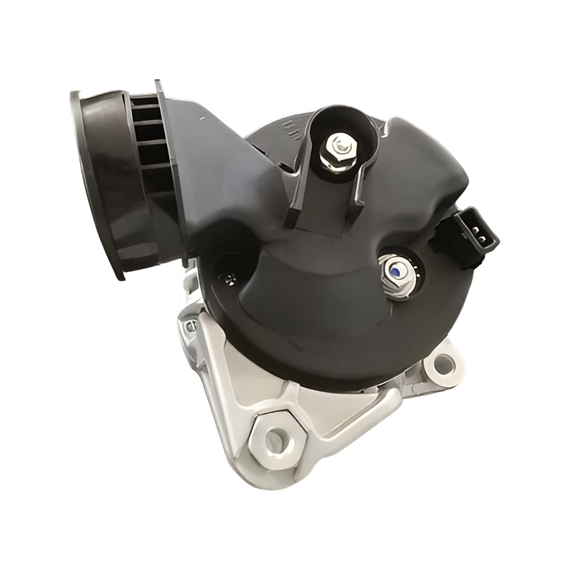 Bosch-Style 12V 120A Alternator for BMW E46 M52B20Product model ZKM81239, a 12V 120A replacement alternator for BMW 320/2.0i E46 M52B20, with internal regulator and BMW/Bosch reference numbers.View Product →
Denso-style units
Denso designs often use a segmented conductor stator and a more integrated rear assembly, with the rectifier and regulator sandwiched under the end frame. Their exploded views show fewer loose parts, so pay close attention to the callouts for terminals and the brush block. A 12 V 90 A unit for the Corolla is a typical example from our catalogue and an easy one to compare against your own core.
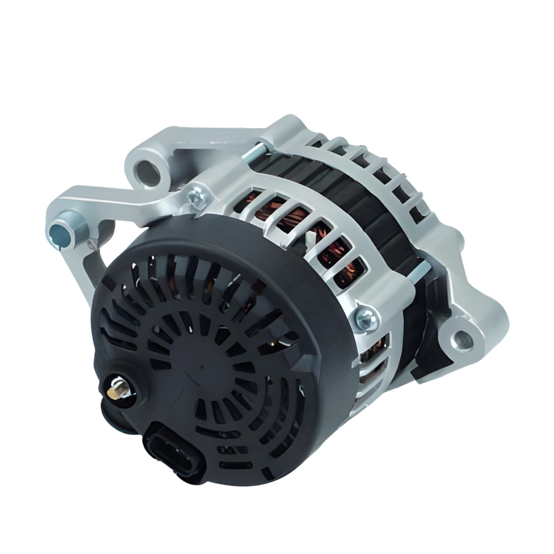 DENSO 12V 90A Alternator for Toyota Corolla 4A 5A 8AProduct model ZKM31163A, a 12V 90A replacement alternator for Toyota Corolla 4A, 5A, and 8A engines with internal regulator and Denso/Toyota references.View Product →
Valeo-style and heavy-duty units
Valeo alternators share a lot of architecture with Bosch on European cars, but the regulator, slip ring housing and brush block are arranged differently, and the body is noticeably shorter. Heavy-duty designs used on trucks and machinery are the friendliest of all to work on: cast housings, larger bearings and a rectifier bridge bolted to the outside of the rear frame. A 12 V 150 A Valeo unit for the BMW 1 Series shows how much of the same hardware can be packed into a much smaller body.
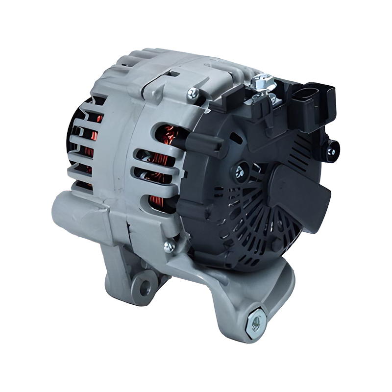 Valeo 12V 150A Alternator for BMW 118 2.0 E81 M47D20Product model ZKM80046, a 12V 150A replacement alternator for BMW 118 2.0 E81 2006-2012 M47D20, with internal regulator and Valeo/BMW references.View Product →
Using an Exploded View for Diagnosis and Repair
- Match numbers, not looks. Two alternators can appear identical from the outside yet differ in pulley offset, fan type and regulator plug.
- Photograph the unit before you open it, then lay the parts out in the drawing's order so reassembly follows the picture instead of your memory.
- Test before you dismantle. A diode check and a field current measurement say more about a charging fault than any amount of visual inspection.
- Replace bearings in pairs. Front and rear wear at different rates, but a new front bearing against a tired rear one will still rumble.
- Respect the small parts. Insulating sleeves, spacers and brush springs cost almost nothing, and they are also what vanishes first from a busy bench.
Repair or Replace?
Rebuilding is worth it when the unit is rare, when the housings are sound, or when you simply enjoy the work. It stops making sense when the slip rings are deeply scored, the bearing seats in either housing are worn, or the rectifier has cooked its own potting. At that point a new unit is usually cheaper than the parts and labour needed to save an old one. We manufacture 100% new alternators rather than remanufactured ones, in 12 V and 24 V versions from 20 A to 250 A, covering passenger cars, trucks, buses, forklifts, agricultural and marine engines. You can browse our alternator range by brand and application, and if a diagram in this article matches the core on your bench, the part number stamped on the housing is the fastest way to find its twin.
An exploded view is only a drawing until you use it. Treat it as a map: find the number you need, understand what that part actually does, and let the sequence in the diagram guide the order of your work. Do that, and even a stubborn charging fault turns into a straightforward job you can finish with confidence, whether you are rebuilding a customer's unit or choosing a brand-new replacement that will still be charging years from now.
Related products
-
-
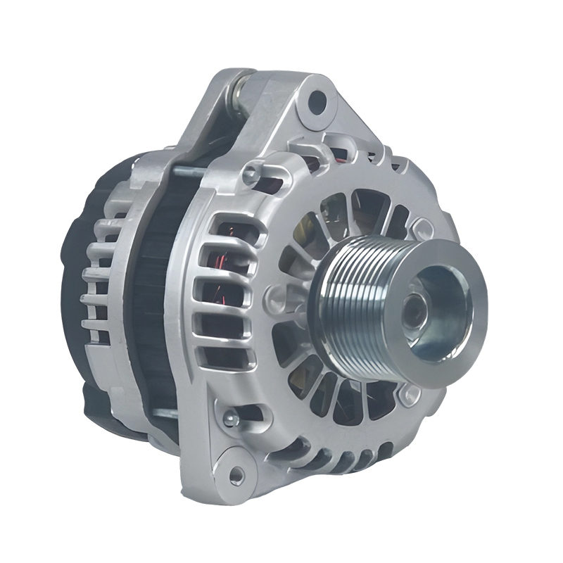
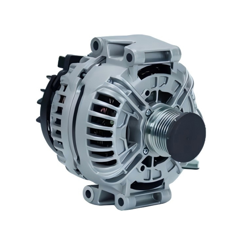
A reliable power solution for commercial and passenger vehicles, the 24V 90A 20289N/0123520500 Bosch car alternator for Hongyan,Genlyon,Saic,lveco,Howo,Weicha is engineered to deliver consistent perfo...
See Details -
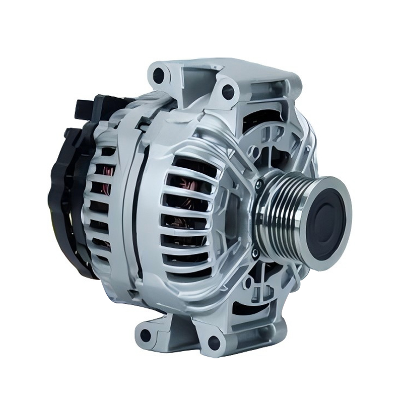
Designed to meet the demanding electrical needs of modern vehicles, the 12V 150A 11064/0124615009 Bosch car alternator for AUDI A4 1.6L, 1.8L, 2.0L is a trusted solution for AUDI A4 owners. Boasting a...
See Details -
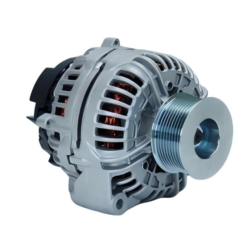
When it comes to keeping your JOHN DEERE 2007-2009 model running smoothly, a reliable alternator is non-negotiable—and the 12V 200A 12796/0124625030 Bosch car alternator for JOHN DEERE 2007-2009 is en...
See Details -
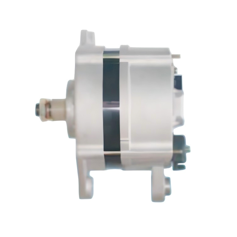
The 24V 55A 12135/0120469978 Bosch car alternator for IVECO EuroCargo EuroTrakker 100E15 90E37 is a reliable power solution specifically engineered for the IVECO EuroCargo EuroTrakker 100E15 90E37 eng...
See Details -
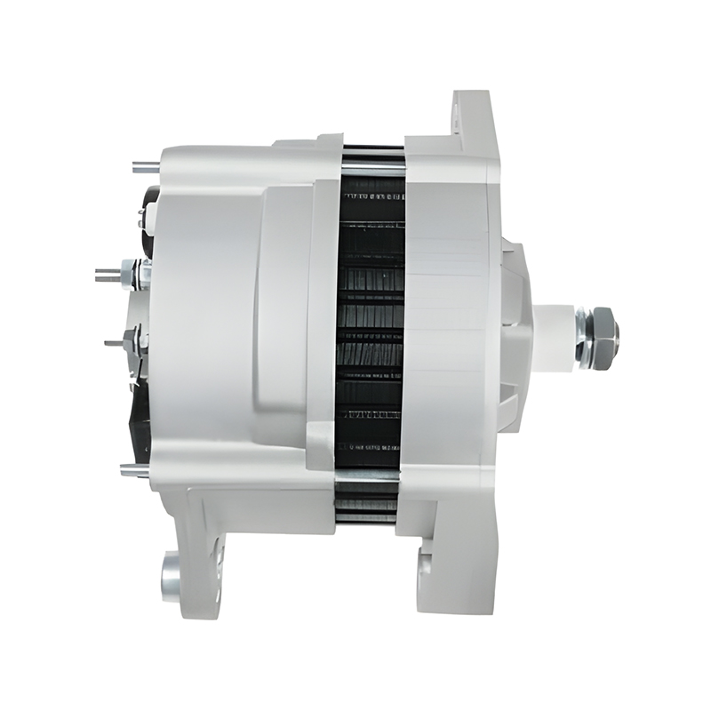
Designed as a reliable power solution for the IVECO 100 E15 engine series, the 24V 80A 12709/0120468116 Bosch car alternator for IVECO 100 E15 combines precision engineering with durable performance t...
See Details

Contact Information
-
Production Plant:No.19, West Taihu Avenue, Wujin District, Changzhou City, Jiangsu Province, China
-
Email:
-
Phone:+86 157 2060 1523
-
TEL:+86-519 8639 0626
Copyright © 2025 Changzhou Hancheng Auto Parts Co., Ltd. All Rights Reserved.
PrivacyAutomotive Alternators Manufacturers High Output Car Alternator Factory
