


 中文简体
中文简体 Español
 Français
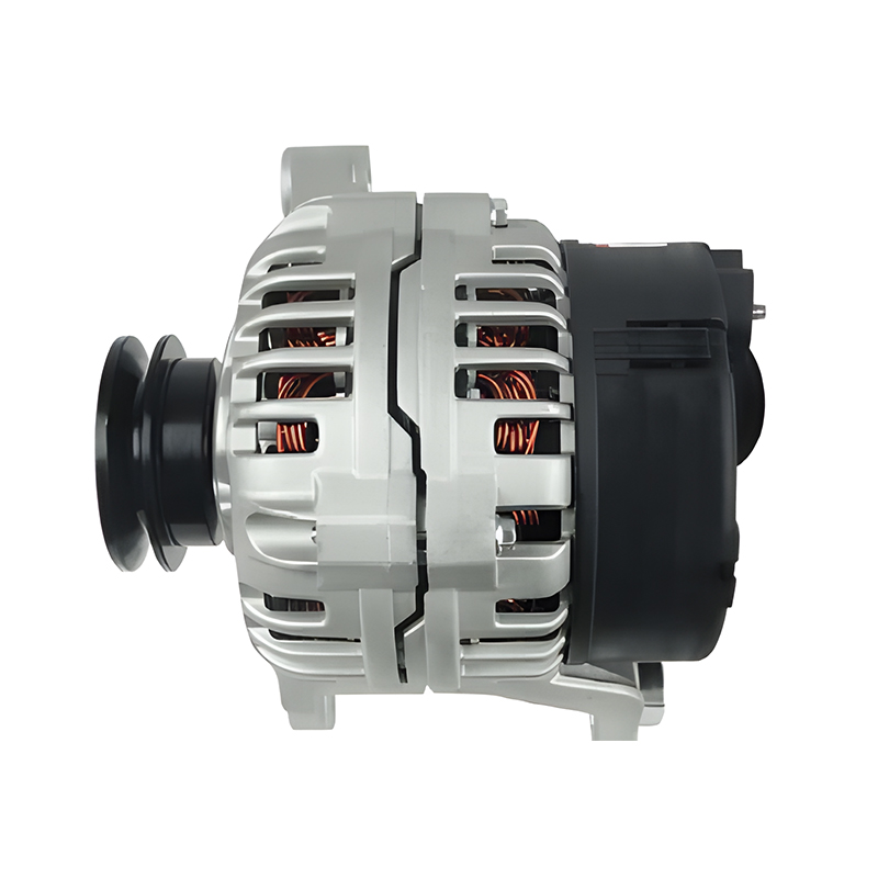
Designed to meet the demanding electrical needs of modern vehicles, the 12V 150A 11064/0124615009 Bosch car alternator for AUDI A4 1.6L, 1.8L, 2.0L is a trusted solution for AUDI A4 owners. Boasting a...
See Details

Get A Quote
Alternator Parts Diagram: Understanding Every Component Inside Your Alternator
Sep 08, 2026
A customer walks in with a charging warning light glowing on the dash. The battery tests fine and the belt is tight, so the alternator gets the blame. Before ordering a replacement, you open the service manual, look at the alternator parts diagram, and trace the unit: pulley at the front, cooling fan behind it, and a cylindrical housing that hides the rotor, stator, rectifier, and voltage regulator. Reading that diagram is not just a classroom exercise; it is how you confirm the diagnosis, explain the repair to the customer, and fit the right unit the first time.
Content
The Main Components at a Glance
An alternator parts diagram is a map of the components that turn mechanical rotation into regulated DC power. Every unit, whether it is fitted to a compact passenger car or a 40-ton truck, uses the same functional groups in the same basic arrangement. Once you can name the parts and their jobs, most charging system faults start to look familiar.
| Part | Function | Typical Failure |
|---|---|---|
| Pulley | Transfers belt drive to the rotor shaft | Groove wear, clutch pulley seizure |
| Cooling fan | Draws air through the housing | Cracked blades, imbalance noise |
| Rotor | Spinning electromagnet that creates the magnetic field | Winding short circuit, worn slip rings |
| Stator | Stationary three-phase windings that produce AC | Burned insulation, open winding |
| Rectifier assembly | Converts AC to DC with a diode bridge | Failed diodes, high output ripple |
| Voltage regulator | Controls rotor current to hold output voltage | Overcharging or undercharging |
| Brushes and slip rings | Feed current to the rotor winding | Worn brushes, intermittent output |
| Bearings | Support the rotor shaft at both ends | Growling noise, shaft play, seizure |
| Housing | Encloses the assembly and mounts it to the engine | Cracks, stripped mounting lugs |
Inside the Housing: Core Components Explained
Understanding how a car alternator works makes the parts diagram much easier to read. The engine turns the pulley, the pulley turns the rotor, and the spinning magnetic field generates current in the stator. Here is what each major component actually does.
Rotor: The Rotating Electromagnet
The rotor sits on the shaft and is driven directly by the pulley. DC current flows through carbon brushes and slip rings into the rotor winding, turning it into an electromagnet. When the shaft spins, that magnetic field sweeps past the stator windings, and the strength of the field controls how much voltage the alternator produces. In a 12V passenger car unit the field current is only a few amps; a 24V truck alternator follows the same principle but uses larger windings designed for a different voltage class.
Stator: Where the Current Is Generated
The stator is a set of three-phase windings fixed inside the housing. As the rotor turns, the moving magnetic field induces alternating current in these windings. The number of turns and the lamination stack determine the output capacity of the alternator. A stator with burned insulation is one of the most common reasons an alternator is replaced outright; once the winding varnish fails, an economical repair is rarely possible.
Rectifier: Turning AC into DC
The battery and the vehicle electrical system need DC, but the stator produces AC. The rectifier assembly, usually a three-phase diode bridge, converts the AC to DC. If a diode fails, the alternator may still produce voltage, but with high ripple that causes flickering lights and hard-to-trace electrical faults in modern vehicles. A quick diode test with a multimeter can confirm the condition while the unit is sitting on the bench.
When internal parts such as a rectifier or stator fail, most workshops choose a complete new alternator instead of rebuilding a core with mixed wear. The labor cost and the risk of a second failure usually tip the decision.
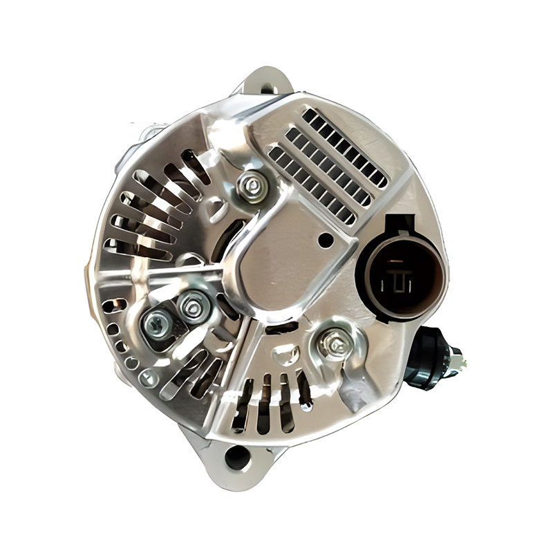 12V 80A Denso Alternator for Toyota Camry with 6-Groove PulleyThis new alternator matches Camry models with a 6-groove pulley and 17 mm shaft. Its internal regulator keeps output near 13.8–14.4 V, making it a reliable replacement when rebuilding an old core is not cost-effective.View Product →
Voltage Regulator: Keeping Output Steady
The regulator monitors system voltage and adjusts rotor excitation to hold output in the correct range: roughly 13.8 to 14.4 volts on a 12V system and 27 to 29 volts on a 24V system. On many modern units the regulator is integrated with the brush holder, so the diagram shows them as a single assembly. A failing regulator produces everything from a chronically drained battery to an overcharged battery that boils electrolyte.
Pulley, Fan, Bearings, and Housing
The pulley transfers belt power to the rotor. On many current applications it is an overrunning alternator pulley that decouples the rotor during rapid engine deceleration, reducing belt wear and noise. The cooling fan is usually pressed on behind the pulley and pulls air through the housing. Two bearings support the rotor shaft, and the housing keeps everything aligned and mounts the unit to the engine. These parts matter most for fitment: an alternator with the correct electrical rating but the wrong mounting pattern or pulley cannot be installed without modification.
How to Read the Terminals on an Alternator Parts Diagram
Besides the internal parts, a practical alternator parts diagram labels the external terminals. These labels show how the unit connects to the vehicle and where to probe during testing.
- B+ (BAT): the main output that charges the battery
- D+ or L: field excitation and the connection used by the charge warning lamp
- IG: ignition-switched power that turns the regulator on
- S: sense terminal that measures battery voltage for accurate regulation
- W: tachometer signal on some units
- B- or ground: the return path for the charging current
Terminal layouts vary from one manufacturer to another, so the safest approach is to match the connector style and pin functions exactly when you order.
Common Failure Points and What the Diagram Reveals
Most alternator failures follow a pattern, and the parts diagram tells you where to look first.
- Worn brushes cause low or zero field current, which shows up as no charging output or an intermittent charge light.
- Failed rectifier diodes produce high AC ripple, which shows up as flickering lights and a battery that never stays fully charged.
- Worn bearings create a growling noise and shaft play, and eventually allow the rotor to contact the stator.
- A burned stator winding usually comes from long-term overloading or a failed regulator that forced the stator to overheat.
- A seized overrunning pulley causes belt squeal and vibration even when the electrical output is still correct.
Once these components fail, rebuilding the old core is rarely worth the labor. A brand-new alternator with fresh rotor, stator, rectifier, brushes, and bearings removes the uncertainty that comes with remanufactured units.
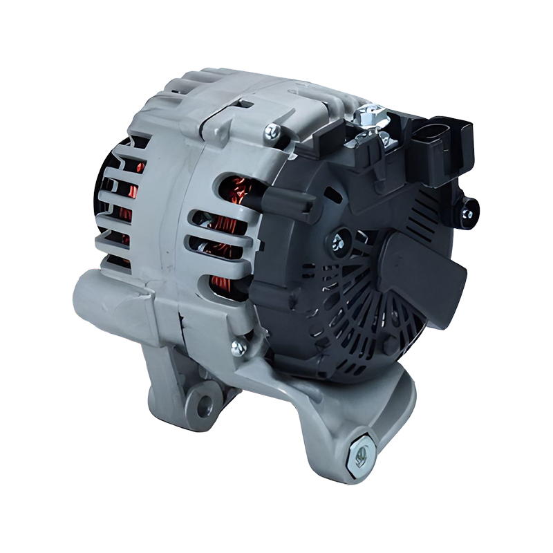 12V 150A Valeo Alternator for BMW 118i E81 M47D20Designed for the BMW 118 2.0 E81 with M47D20 engine, this 150 A unit includes an internal regulator and fits original mounting points. It avoids the uncertainty of remanufactured cores by providing fresh components throughout.View Product →
Check These Points Before You Order
An alternator parts diagram helps you confirm that a replacement unit will physically fit and deliver the current the vehicle needs.
- Voltage: 12V or 24V must match the vehicle system.
- Current rating: at least equal to the original, and higher for vehicles with added electrical loads.
- Mounting style and lug positions: a similar photo is not enough; check the reference number.
- Terminal layout and connector type: the wiring harness plug must match.
- Pulley and fan: confirm whether they are included or must be transferred from the old unit.
Output current becomes critical when loads have been added: auxiliary lighting, inverters, electric cooling fans, or a winch. For those vehicles, a high-output alternator with a stronger stator and a heavier rectifier is the correct choice. Stock vehicles can stay with the original amperage.
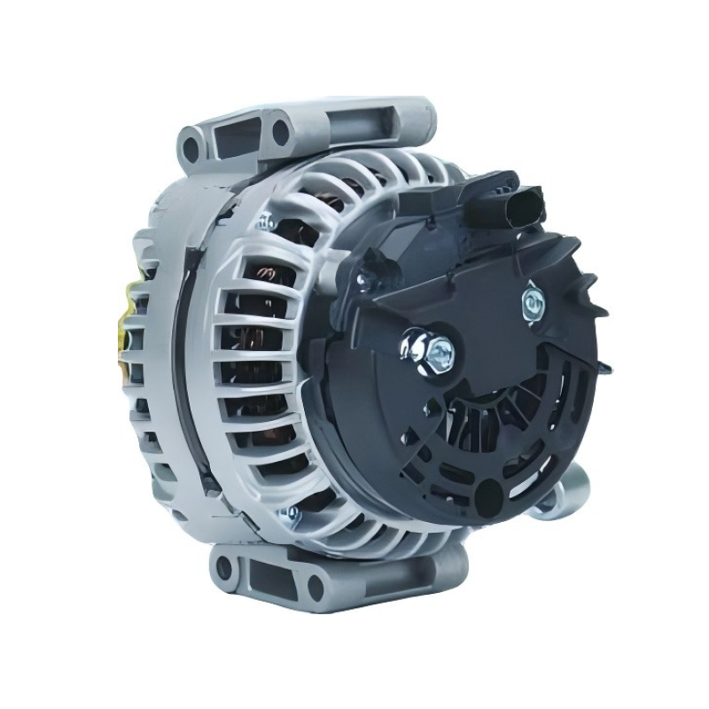 12V 200A Bosch Alternator for Mercedes Sprinter, Vito, Viano CDi 2.1LA high-output 200 A alternator suited to Mercedes CDi 2.1L vans and light commercials with added electrical loads. Built as a new unit with Bosch engineering, it suits workshops needing predictable quality for heavy-duty use.View Product →
For aftermarket buyers, the manufacturer matters as much as the part number. An alternator built as a 100% new unit starts with new rotor, new stator, new rectifier, and new bearings; a remanufactured unit is only as good as the core it was built from. That is why workshops and distributors who need predictable quality source from a factory that controls the whole assembly process. To check specifications against your application, browse the complete alternator range on our site.
Related products
-
-
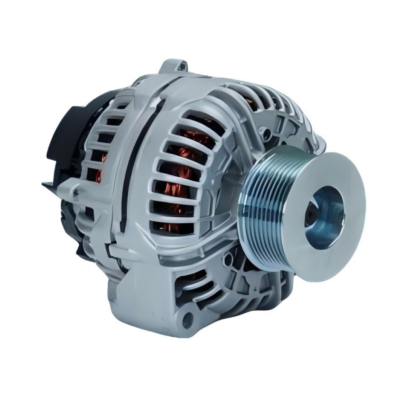
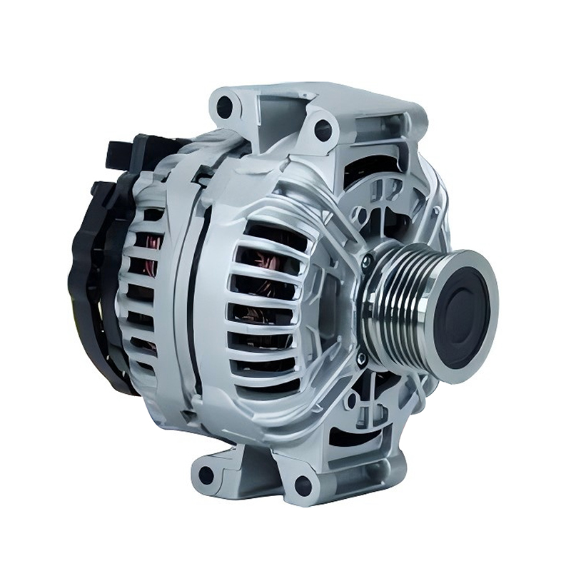
When it comes to keeping your JOHN DEERE 2007-2009 model running smoothly, a reliable alternator is non-negotiable—and the 12V 200A 12796/0124625030 Bosch car alternator for JOHN DEERE 2007-2009 is en...
See Details -
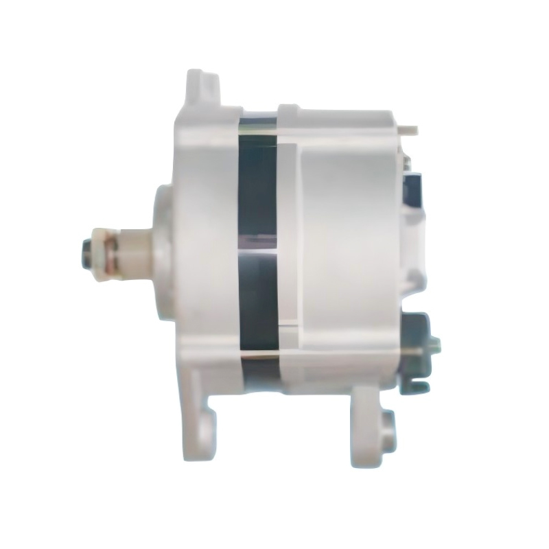
The 24V 55A 12135/0120469978 Bosch car alternator for IVECO EuroCargo EuroTrakker 100E15 90E37 is a reliable power solution specifically engineered for the IVECO EuroCargo EuroTrakker 100E15 90E37 eng...
See Details -
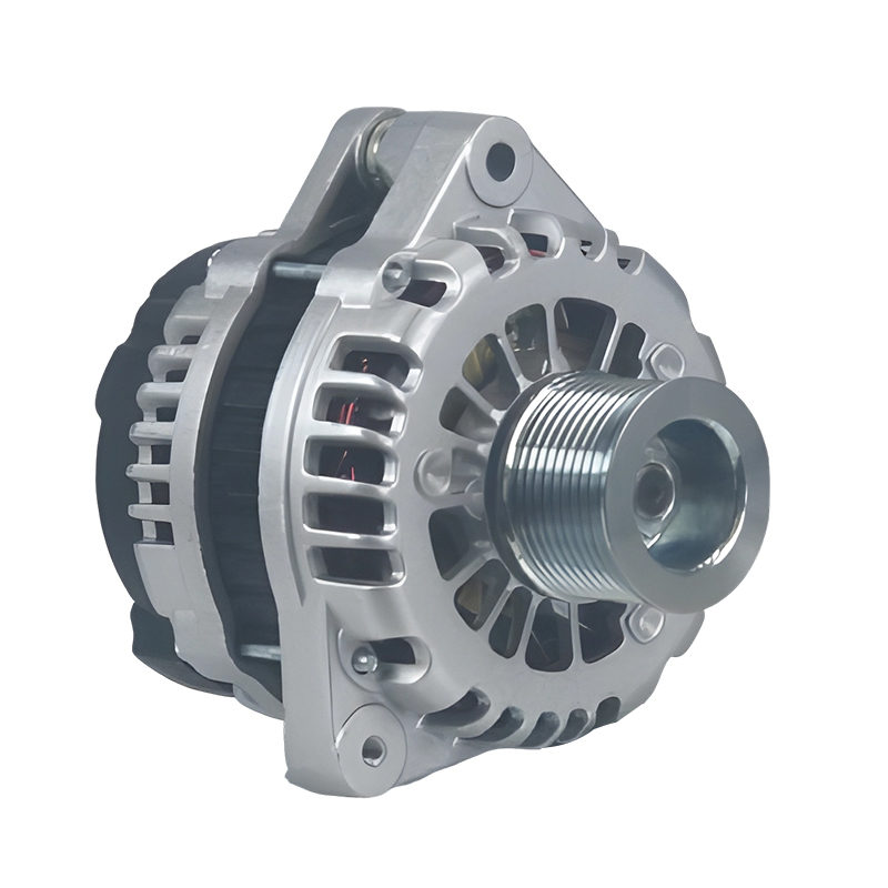
A reliable power solution for commercial and passenger vehicles, the 24V 90A 20289N/0123520500 Bosch car alternator for Hongyan,Genlyon,Saic,lveco,Howo,Weicha is engineered to deliver consistent perfo...
See Details -
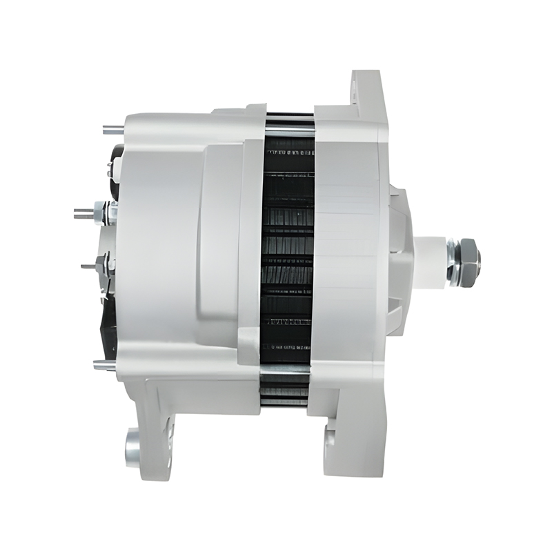
Designed as a reliable power solution for the IVECO 100 E15 engine series, the 24V 80A 12709/0120468116 Bosch car alternator for IVECO 100 E15 combines precision engineering with durable performance t...
See Details -
The 12V 90A 0123315503/112406 Bosch car alternator for IV ECO DAIY is a high-quality replacement part specifically designed for the IV ECO DAIY engine series, offering reliable performance to meet the...
See Details

Contact Information
-
Production Plant:No.19, West Taihu Avenue, Wujin District, Changzhou City, Jiangsu Province, China
-
Email:
-
Phone:+86 157 2060 1523
-
TEL:+86-519 8639 0626
Copyright © 2025 Changzhou Hancheng Auto Parts Co., Ltd. All Rights Reserved.
PrivacyAutomotive Alternators Manufacturers High Output Car Alternator Factory
