


 中文简体
中文简体 Español
 Français
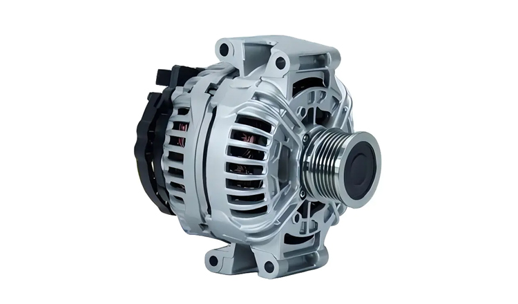
Designed to meet the demanding electrical needs of modern vehicles, the 12V 150A 11064/0124615009 Bosch car alternator for AUDI A4 1.6L, 1.8L, 2.0L is a trusted solution for AUDI A4 owners. Boasting a...
See Details

Get A Quote
Alternator Components Diagram: A Complete Guide to Every Part
Aug 05, 2026
When a vehicle's electrical system starts acting up—dimmer headlights, a warning light on the dash, or a battery that keeps dying—the alternator is usually the first suspect. But before you order a replacement, it helps to know what is actually inside the unit and how those parts work together. An alternator components diagram does more than satisfy curiosity; it gives you a mental map for diagnosing problems, comparing quality, and making smarter purchasing decisions.
Here is the short version: an alternator converts mechanical energy from the engine into electrical energy to charge the battery and power the vehicle's electrical loads. The key components—rotor, stator, rectifier, voltage regulator, brushes, and slip rings—each play a specific role in that process. When one of them fails, the symptoms are often distinctive enough to pinpoint the culprit. This guide breaks down every part, explains how they function in sequence, and shows you how to use that knowledge when choosing a replacement. As a manufacturer of 100% new, high-output alternators, we will also point out where component quality matters most.
Content
- 1 What Is an Alternator and Why Do Its Components Matter?
- 2 Alternator Components Diagram: Full Overview
- 3 How Each Alternator Component Works (Step by Step)
- 4 Alternator Wiring Diagram: Connecting the Terminals
- 5 How to Identify a Failing Component Using the Diagram
- 6 Standard vs. High-Output Alternators: Component Differences
- 7 Choosing a Quality Replacement: What to Look For
- 8 Conclusion
What Is an Alternator and Why Do Its Components Matter?
Think of the alternator as the electrical power plant of your vehicle. The engine turns a belt connected to the alternator's pulley; inside, that rotational energy is transformed into electricity that keeps the battery charged and runs everything from the ignition system to the headlights and infotainment. Without a functioning alternator, the battery alone would drain within minutes.
Why should you care about the internal components? Because knowing what is inside helps you in two practical ways. First, when a charging system fault appears, you can narrow down the cause by symptom rather than guessing. Second, when you shop for a new unit, you can evaluate whether the manufacturer used quality materials in the places that matter—like the rectifier diodes and stator windings. Understanding how a car alternator works is the foundation; learning the component layout builds on that knowledge.
As a factory that builds 100% new alternators rather than rebuilt units, we see the difference component quality makes on a daily basis. Fresh parts installed to factory specifications simply last longer and perform more consistently than remanufactured units with mixed-age internal parts.
Alternator Components Diagram: Full Overview
Before diving into each part's function, it helps to see the whole picture. An alternator components diagram typically shows both the external case and the internal layout. Here is the full lineup:
External Parts: Pulley, Housing, and Terminals
From the outside, you are looking at the housing, the pulley, and the electrical terminals. The housing is usually die-cast aluminum—lightweight, excellent at dissipating heat, and non-magnetic. The pulley sits at the front and transfers engine power to the rotor shaft via the drive belt. Ventilation slots in the housing allow internal fans to pull air through and cool the components.
The terminals are your connection points to the vehicle's wiring. While configurations vary by manufacturer, most alternators use a standardized set of terminals:
- B+ (Battery Positive): The main output terminal that connects directly to the battery positive terminal.
- D- (Ground): The ground connection for the charging circuit.
- D+ (Charge Indicator): Connects to the warning light or sense circuit.
- S (Sense): Senses battery voltage to help the regulator adjust output.
- IG (Ignition): Receives ignition-switched power to energize the field circuit.
- L (Lamp): Drives the charge warning light on the dash.
- F (Field): Connects to the field winding or regulator controls.
Not every unit has all of these, but B+ and D- are universal. The others depend on the vehicle manufacturer's design and the regulator type.
Internal Parts: Rotor, Stator, Rectifier, and Regulator
Inside the housing, the core components are arranged around a central shaft. The rotor is the spinning part, wound with copper wire and shaped like claws around the shaft. The stator is a stationary ring of copper windings that surrounds the rotor. The rectifier (usually a heat-sinked assembly of diodes) sits near the rear of the case. Next to it, the voltage regulator controls field current to keep output steady. Brushes and slip rings carry the initial excitation current to the rotating rotor winding.
How Each Alternator Component Works (Step by Step)
Generating electricity in an alternator happens in four distinct stages. Each stage depends on specific components working in sequence.
Step 1: Pre-Excitation. When you turn the ignition key, battery voltage flows through the charge warning light circuit to the regulator, then through the brushes and slip rings into the rotor winding. This initial current creates a weak magnetic field around the rotor.
Step 2: Generation. The engine turns the pulley, which spins the rotor inside the stator. As the rotor's magnetic field sweeps past the stator's three-phase windings, it induces alternating current (AC) in those windings. The faster the rotor spins and the stronger the field current, the higher the AC voltage produced.
Step 3: Rectification. AC is not usable by your vehicle's electrical system, which runs on DC. The rectifier—a bank of six or more diodes—converts the AC output into DC. Three of the diodes handle the positive half of each phase; three handle the negative. In many designs, three additional "field diodes" provide a dedicated DC supply for the rotor's excitation circuit.
Step 4: Regulation. The voltage regulator continuously samples the system voltage (via the S terminal) and adjusts the rotor's field current. If voltage is low, it increases field current to boost output; if voltage is high, it reduces field current. This keeps the system around 13.5–14.5V for a 12V system, regardless of engine RPM or electrical load.
The Role of Brushes and Slip Rings
Brushes and slip rings are the bridge between the stationary electrical circuits and the spinning rotor. Two small carbon brushes press against two smooth copper rings mounted on the rotor shaft. This sliding contact delivers DC current to the rotor winding, enabling the magnetic field that makes generation possible.
These are the most wear-prone parts in an alternator. Brushes are designed to last, but they do erode over time—typically after 80,000 to 150,000 miles. When they wear out, you will notice symptoms like inconsistent charging, a flickering charge light, or a whining noise from the alternator area. Replacing brushes alone is possible, but at that mileage, other components like bearings and diodes are often close to end-of-life too. That is why many technicians recommend replacing the entire alternator rather than just servicing the brushes. If you want to understand the full scope of routine care, our alternator maintenance and repair guide covers the common wear points in more detail.
Alternator Wiring Diagram: Connecting the Terminals
For anyone working on their own vehicle, an alternator wiring diagram is just as important as the parts diagram. The connections tell you how the unit talks to the battery, the ignition switch, and the warning light.
In a typical setup:
- B+ runs through a heavy-gauge wire (often fused) directly to the battery positive terminal or the main fuse box.
- D+ connects to the charge warning lamp, which is then connected to ignition-switched power. When the engine is off, the lamp circuit completes the field excitation path.
- S senses battery voltage through a dedicated wire to help the regulator maintain the correct setpoint.
- IG receives ignition power to enable the regulator circuit.
- Ground is established through the case body connected to the engine block, plus the D- terminal where present.
Some modern alternators use a smart charge system with LIN communication or PWM control, but the physical terminals remain similar. Always verify the wiring against your vehicle's service manual, because incorrect connections can damage the regulator or diodes.
How to Identify a Failing Component Using the Diagram
The alternator components diagram is your diagnostic map. Different failure modes point to different internal parts. Here is a practical breakdown of symptoms and their likely culprits:
| Symptom | Likely Failing Component | Repair Decision |
|---|---|---|
| Whining or grinding noise from the alternator | Bearing or worn brushes | Replace the alternator; bearing failure often damages the rotor shaft |
| Voltage fluctuates at idle, headlights dim and brighten | Voltage regulator or worn brushes | Test regulator separately; if brushes are worn past 60%, replace the unit |
| No charging at all, battery drains quickly | Rectifier diodes shorted or open | Diodes cannot be repaired individually in most cases; replace the alternator |
| Burning smell accompanied by excess heat | Stator winding shorted or overheated | Stator failure means the unit is not worth rebuilding; replace it |
| Charge light stays on but battery tests fine | Regulator or field circuit issue | Check brush wear first, then test the regulator circuit |
| Battery overcharges, fluid boils out | Voltage regulator stuck in high-output state | Regulator failure can ruin the battery; replace the alternator promptly |
If you are seeing these symptoms, it is worth reviewing a broader list of common vehicle alternator problems to cross-check your diagnosis. In most cases, once a major component like the stator or rectifier has failed, replacing the entire alternator costs less and is more reliable than a full rebuild.
Standard vs. High-Output Alternators: Component Differences
Not all alternators are built the same internally. A high-output model—one rated at 150A, 200A, or even 250A—differs from a standard 80A unit in several key components:
- Stator windings: High-output units use thicker gauge copper wire and a denser winding pattern to handle higher current without overheating.
- Rectifier capacity: Larger diodes with bigger heat sinks are necessary to dissipate the extra heat generated by high current flow.
- Fans and cooling: High-output alternators often have dual internal fans or enlarged ventilation slots to move more air over the components.
- Rotor design: A stronger magnetic field requires more copper on the rotor and sometimes a heavier shaft to manage the additional magnetic stress.
These differences matter if you have added electrical loads: a high-power audio system, auxiliary lighting, a winch, or a vehicle used for fleet duty with heavy parasitic draws. If you are considering an upgrade, our comparison of standard vs. high-output alternators explains the decision framework in detail. As a manufacturer specializing in high-output units, we design our products with these heavier-duty components from the start. For applications ranging from light trucks to commercial buses, you can find Mitsubishi alternators for your vehicle from our lineup that deliver the higher amperage your system needs.
Choosing a Quality Replacement: What to Look For
When you open the box on a new alternator, the physical condition of the parts tells you a lot about its quality and expected lifespan. Here is what to check:
- Copper, not aluminum: High-quality stators and rotors use pure copper windings. Some low-cost units substitute aluminum, which increases resistance and reduces output efficiency.
- Rectifier build quality: Look for soldered or crimped copper terminals on the diodes, not spade connectors that can loosen over time.
- Rotor balance: A properly balanced rotor spins smoothly without vibration. Poor balance accelerates bearing wear.
- Housing and fins: A well-designed aluminum housing with adequate vent fins indicates the manufacturer planned for heat management.
- New parts, not remanufactured: "100% new" means every component inside is fresh—not just cleaned or reused. This eliminates the uncertainty of mixed-age parts common in rebuilt units.
At our factory, every unit we ship is built from new components to meet the original equipment specifications of the brand it replaces. If you are ready to move from understanding the parts to selecting an actual unit, browse our Bosch car alternator collection to find a model that matches your vehicle's application and amp rating.
Conclusion
An alternator components diagram is more than a technical illustration—it is a practical tool for every vehicle owner and technician. When you know that the rotor builds the magnetic field, the stator converts it to AC, the rectifier turns that into usable DC, and the regulator keeps everything stable, you can approach any charging system problem with confidence. You also become a more informed buyer. The difference between a 100% new, high-output alternator and a budget rebuilt unit lies in the quality of these internal components. That difference shows up in reliability, output consistency, and how many years the unit lasts. Use the diagram as your reference, and when replacement time comes, you will know exactly why the internal parts matter.
Related products
-
-
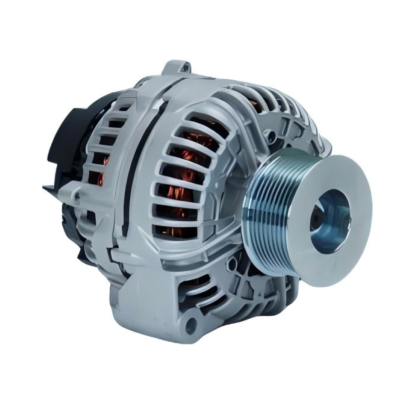
When it comes to keeping your JOHN DEERE 2007-2009 model running smoothly, a reliable alternator is non-negotiable—and the 12V 200A 12796/0124625030 Bosch car alternator for JOHN DEERE 2007-2009 is en...
See Details -
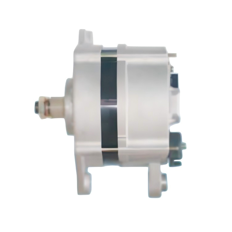
The 24V 55A 12135/0120469978 Bosch car alternator for IVECO EuroCargo EuroTrakker 100E15 90E37 is a reliable power solution specifically engineered for the IVECO EuroCargo EuroTrakker 100E15 90E37 eng...
See Details -
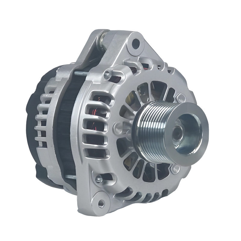
A reliable power solution for commercial and passenger vehicles, the 24V 90A 20289N/0123520500 Bosch car alternator for Hongyan,Genlyon,Saic,lveco,Howo,Weicha is engineered to deliver consistent perfo...
See Details -
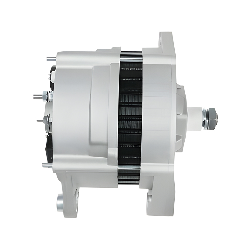
Designed as a reliable power solution for the IVECO 100 E15 engine series, the 24V 80A 12709/0120468116 Bosch car alternator for IVECO 100 E15 combines precision engineering with durable performance t...
See Details -
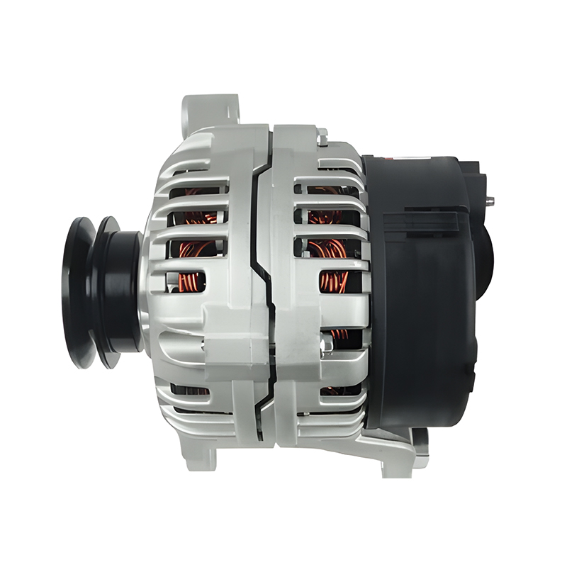
The 12V 90A 0123315503/112406 Bosch car alternator for IV ECO DAIY is a high-quality replacement part specifically designed for the IV ECO DAIY engine series, offering reliable performance to meet the...
See Details

Contact Information
-
Production Plant:No.19, West Taihu Avenue, Wujin District, Changzhou City, Jiangsu Province, China
-
Email:
-
Phone:+86 157 2060 1523
-
TEL:+86-519 8639 0626
Copyright © 2025 Changzhou Hancheng Auto Parts Co., Ltd. All Rights Reserved.
PrivacyAutomotive Alternators Manufacturers High Output Car Alternator Factory
